ST7735 displays
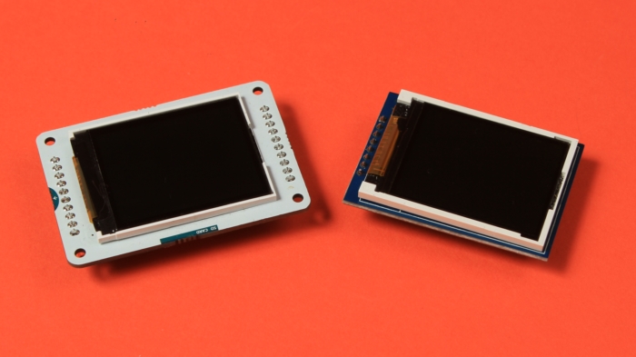
The ST7735 display is a TFT LCD that is controlled by the ST7735/ST7735S/ST7735B micro-chip driver, which acts as a bridge between the display matrix and the microcontroller. These colorful displays are cheap, easy to connect and control. Therefore, they spread widely in the Arduino world and their popularity gave rise to many breakout board variations.
The displays breakout boards belong to the ST7735 family can have the following parameters:
- Display resolution:
- 0.96" (80x160 pixels);
- 1.44" (128x128 pixels);
- 1.8" (128x160 pixels);
- Display colors (Color mode):
- 16-bit “High color”, 65,536 colors;
- 18-bit, 262,144 colors;
- Interfaces:
- SPI interface (software of hardware);
- Parallel MCU interface (8-bit, 9-bit, 16-bit & 18-bit);
To work with the ST7735 family displays XOD provides the xod-dev/st7735-display library.
Quick start nodes #
ST7735 breakout boards can differ from each other and require different initialization methods. Therefore, the xod-dev/st7735-display library contains 4 quickstart nodes at once - st7735-128x160-b, st7735-128x160-g, st7735-128x160-rg, and st7735-128x160-rr. Each of these nodes works with a display of a certain type conventionally named “B”, “G”, “RG”, and “RR”. To find out which type your specific display belongs to, try each of these nodes until it works.
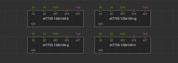
Wire your display to the microcontroller via hardware SPI bus and fill in the CS, DC, RST pin values according to the microcontroller ports. The CS is the “Chip Select” microcontroller port of the SPI interface. DC is the “Data/Command” microcontroller port responsible for sending data and commands to the display driver.
The RST pin is the “Reset” microcontroller port the display is connected to. This port is responsible for the display reset which can be required during device initialization. Not all ST7735 breakout boards have this pin. If your ST7735 breakout board has this pin, be sure to link it with a microcontroller and set the appropriate port value at the RST pin. If your breakout board does not have an RST pin, then leave the D255 default value untouched.
The GFX input pin of the graphics type specifies the graphics to render and display on the device screen. The GFX awaits a branch of the tree of graphical elements created using the graphics library. The boolean value at the ACT pin is responsible for the display screen update due to change of the incoming graphics at the GFX pin.
Quick start example #
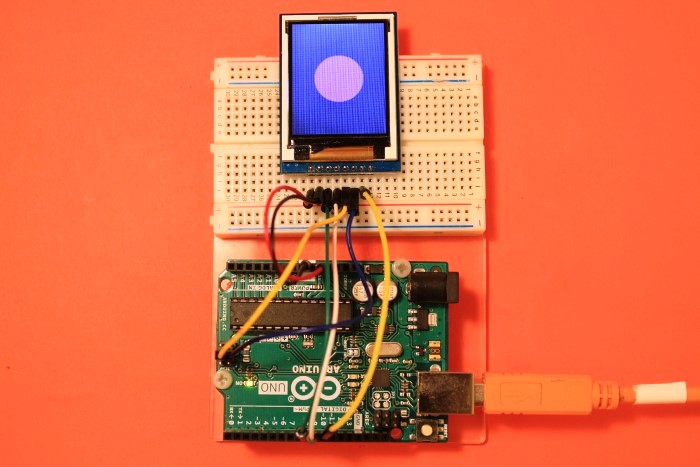
Here is a simple example of using quickstart nodes. For example, We use an ST7735 128x160 SPI display of a “G” type. Connect it to a microcontroller according to the wiring scheme.
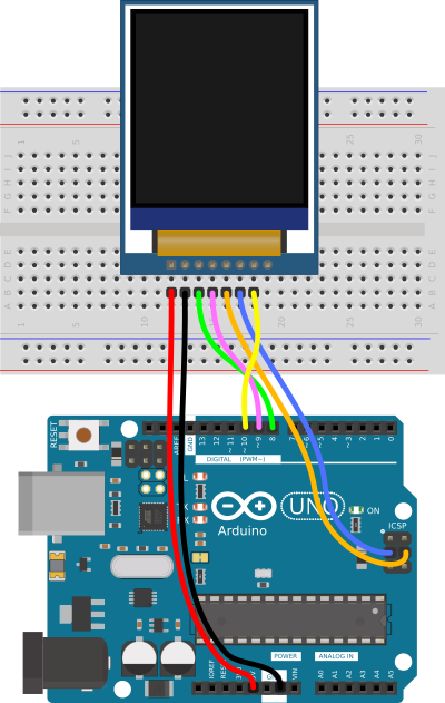
Use the hardware SPI bus. Connect the display’s CS pin to the D10 controller port, and the DC pin to the D9 port. The breakout board of the display used in this example has an RST pin, so it should be wired. The RST pin is connected to the D8 port.
Let’s display a pink filled circle in the center of the screen.
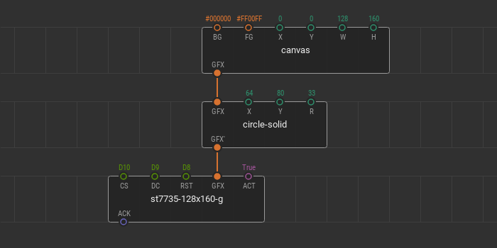
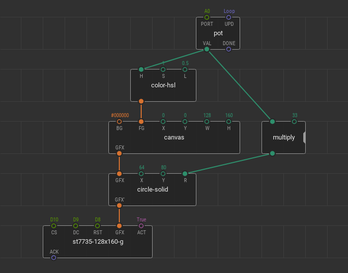
Put the quickstart node st7735-128x160-g onto the patch and fill in ports values CS, DC, and RST according to the wiring scheme. Using the XOD graphics library, create a new canvas with the size of a display screen. The width W of the canvas is 128 and the height H is 160. The background color BG is set to black (#000000) and the foreground color FG to pink (#FF00FF).
To add the filled circle to the scene, place the circle-solid node onto the patch. To make this node be a part of the graphic tree, link its GFX pin with the GFX pin of the canvas. Set the circle coordinates for the center of the screen, 64 for X, and 80 for Y. The radius R can be random, for example, 33.
The scene is ready. Connect the GFX output pin of the circle-solid node to the GFX pin of the quickstart node. Take a look at what the patch should be.
Upload this patch and see what is displayed on the screen of the device.
You can change all parameters of the graphic nodes in a real-time. For example, you can change the position of the circle or the background color of the canvas using tweaks. Add two tweak-number nodes for the X and Y circle coordinates. Add the tweak-color node for the BG pin. Flash the patch in debug mode and manage colors and coordinates.
The parameters of graphic nodes can be changed using other nodes. For example, you can change the color of the circle and its size using a potentiometer. Remove tweak nodes from the patch. Place new nodes pot, multiply, and color-hsl node from the xod/color library. Connect the potentiometer to the A0 Arduino port.
With the combination of pot and multiply, the R radius of the circle changes from 0 to 33 pixels. With the combination of pot and color-hsl, the H hue of the FG foreground color of the canvas changes from 0 to 1. Upload the patch and manage the graphics changes.
Advanced LCD device initialization #
If the quickstart nodes doesn’t suit your task try to operate some developer nodes from the xod-dev/st7735-display library. Initializie your display using the device nodes from the library - st7735-128x160-b-device, st7735-128x160-g-device, st7735-128x160-rg-device, and st7735-128x160-rr-device.
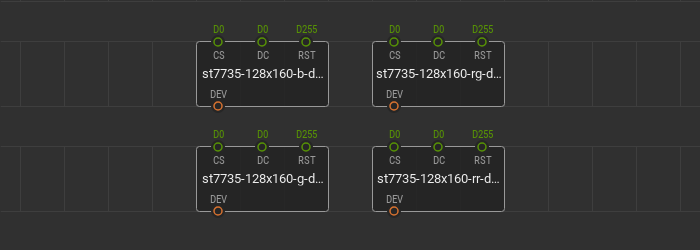
As the quickstart nodes, these device nodes init a display of a particular type conventionally named “B”, “G”, “RG”, and “RR”. If you don’t know the exact type of display you have, determine it by sampling different device nodes. With one of them, your display starts working, and you get the type.
Rotate the screen #
You can change the screen position and the origin of the display coordinate system with the rotate node.
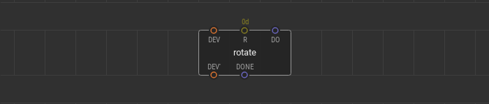
The rotate node allows you to rotate the display screen to one of four positions: 0 degrees portrait, 90 degrees landscape, 180 degrees portrait, and 270 degrees landscape. A value at the P pin sets the angle to rotate the screen and can be one of four values 0d, 1d, 2d, 3d. These values correspond to the particular display positions.
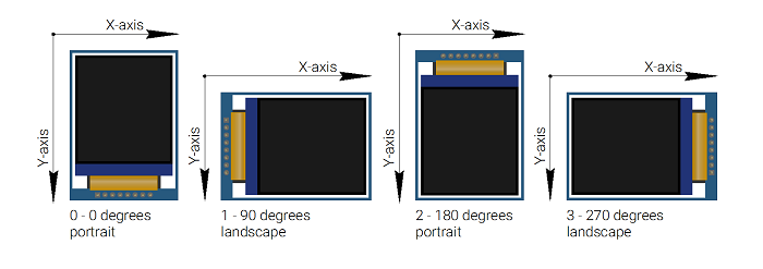
A pulse type signal at the DO pin triggers a new screen rotation and the coordinate system change. The pulse at the DONE output pin signals that the rotation is complete. The rotate can be used in run-time and at any step of the program. It is possible to use several rotate nodes.
Render the scene #
The render node is your main tool to display graphic scenes. The render processes a single branch of the graphic tree created using the graphics library, renders it, and displays at the device.
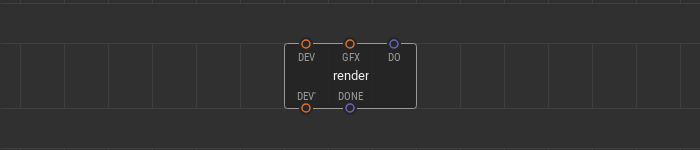
A graphic tree branch to render links to the input GFX pin. A pulse signal at the DO pin is a trigger to process the graphic scene and display it. If the scene is rendered, a pulse comes to the DONE output pin.
Use multiple render nodes simultaneously. Processing various branches of the graphic tree at a different time, you can show dynamic graphic scenes at the screen.
Here is the example of a three render nodes use. The tree of graphic elements consists of a canvas and two point on it. The device node and three nodes render are linked together in a daisy chain. All render nodes have different triggering algorithms at their DO pins.
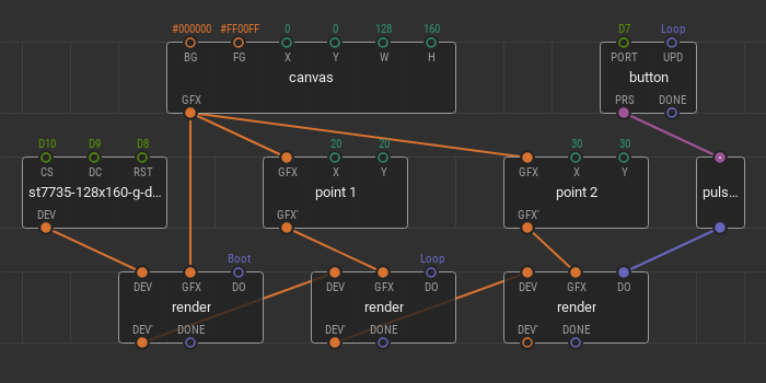
The first render is on boot; it fills the display screen with a specified canvas only once — after powering the device. The second render is responsible for point 1 on the canvas. Its trigger is set to loop. It means that any changes in the point 1 position are immediately shown on the screen. The third render is responsible for displaying the point 2 and its trigger is linked to the button. Here you can also change the point 2 position, but the changes are displayed only after the button click.