Digital Clock Example — Working with RTC Modules
This example describes how to use the datetime and ds-rtc libraries, format date and time values, and work with real-time clock (RTC) modules for Arduino. Upon the completion of this guide, you will learn how to create a simple digital clock based on a DS1307 I2C RTC module and I2C LCD display.
Required hardware #
- Arduino Uno board
- I2C RTC breakout board based on the DS1307 microchip
- I2C LCD 16x2 display
- A battery to power the RTC module
- Breadboard
- Hook-up wires
You can use a DS3231 or DS1302 breakout board instead of DS1307 because they are interchangeable.
Circuit #
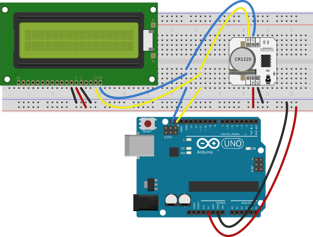
- Both the I2C display and the real-time clock board communicate via I2C. To ease the connection, you can create the I2C bus on the breadboard by wiring the
SDLandSDAI2C pins from the Arduino board to the contact lines on the breadboard. The display and RTC have different I2C addresses, they do not interfere with each other, so you can connect them to the same I2C bus. - Connect the
GNDand5Vpins from the Arduino board to the corresponding rails on the breadboard. - Plug the I2C display. Wire its
SDAandSDLwith the I2C bus on the breadboard. Wire itsGNDandVopins with theGNDline on the breadboard. WireVccpin with the5Vline on the breadboard. - Plug the I2C RTC breakout board. Wire its
SDAandSDLwith the I2C bus on the breadboard. Wire itsVandGNDpins with the corresponding lines on the breadboard. - Power the RTC board with the battery to keep running even when the external power source is disconnected.
If you are using another model of the I2C display or RTC module, look at their pinout and datasheet to connect them correctly.
Programming steps #
For this example, the programming process consists of two steps:
- Making a program to write the current datetime to the memory of the RTC module.
- Making a program to read the current datetime from the RTC module and display it on the screen.
Writing datetime #
Create a new patch set-current-time. We’ll use it only once to write the current time to the memory of RTC module so that it has a proper base point.
- Put an
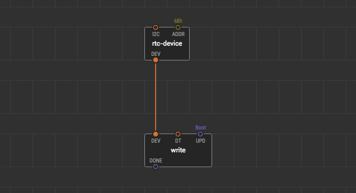
rtc-devicenode from thexod-dev/ds-rtclibrary onto the patch. This node describes an RTC breakout board which communicates via I2C. By default, the I2C device address of the RTC at theADDRpin is68hwhich is correct for the most DS1307 modules. TheDEVpin of the node outputs thertc-devicevalue which contains everything to operate the device. - Add a
writenode from thexod-dev/ds-rtclibrary onto the patch. This node’s function is to write time and date to the permanent memory of the RTC board. TheDTpin inputs adatetimetype value to be written. TheUPDpin triggers a new write. TheDONEoutput pin notifies writing complete. - Link the
DEVpin of thewritenode with theDEVpin of thertc-devicenode. - The
On bootvalue at theUPDpin means that we write thedatetimeonce after the boot of the device.
The write node requires the date and time values having a datetime type. The datetime node is used to pack year, month, day, and hours, minutes, seconds into a datetime type value.
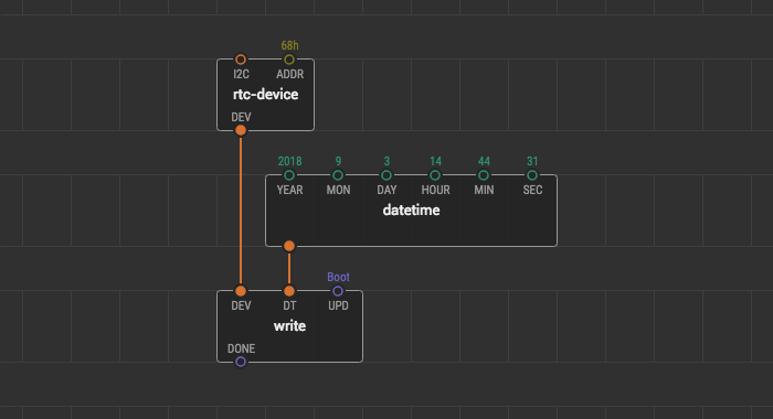
- Put the
datetimenode onto the patch. - Link the output pin of the
datetimenode with theDTpin of thewritenode. - Fill the
YEAR,MON,DAY,HOUR,MIN, andSECpins with values. Each pin contains a description of what form this values should be.
For example, we set the current date. Now it is the 17-th of September of the 2018 year, and the time is 14 hours 44 minutes and about 31 seconds. To set this date and time values to the RTC, we fill the datetime pins with values.
- The
2018year value to theYEARpin. 9number of the September month to theMONpin.17number of the day of the month to theDAYpin.14number of the hours to theHOURpin.44number of the minutes to theMINpin.31number of the seconds to theSECpin.
The patch to set up the real-time clock is completed. Let’s quickly load it into the Arduino board, to make the difference between the real and written time be only a few seconds.
Once the board is flashed the RTC module will get the correct current time value which automatically ticks and not get lost as long as the module is powered by either its battery or the device itself. However, note that the time gets re-written on every boot to that exact value we have set. So, if you will reset your board after an hour, it will overwrite the correct time with the now-obsolete hour-lagging value. To protect from this effect it is a good idea to remove the uploaded time setting program. Upload an empty patch right after set-current-time to clear.
We won’t need the set-current-time patch anymore.
Reading datetime #
Create a new patch and name it digital-clock. This is the patch for our digital clock. Strictly speaking, we are going to create a new program. So we need to put an RTC node again. To fetch the data, a node which is named simply rtc might be used. Then we unpack the obtained values for further work.
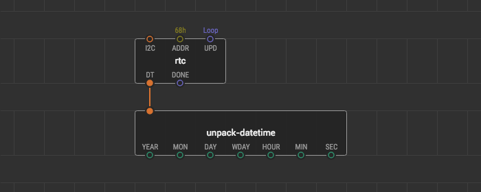
- Add the
rtcnode onto the patch. This node represents an RTC clock. A pulse at theUPDpin triggers a new reading of adatetimetype value. TheDONEoutput pin fires on successful read. By default, the I2C device address at theADDRpin is68h. - For the continuous reading of date and time set the
UPDpin value toContinuous. - Add the
unpack-datetimenode onto the patch and link it with thertcnode. Theunpack-datetimenode destructs thedatetimetype value and outputsNumbervalues of the date and time for subsequent processing or formatting.
Look at descriptions of output pins of the unpack-datetime node to figure out the ranges and formats of the output values.
If the real-time clock takes a small place in your extensive project, and a controller is very loaded, the Continuous pulses on time readings can lead to various unexpected read failures. To solve this problem limit the pulse frequency. For example, you can link the UPD pin with the clock node and set the IVAL value to 1 second. By this, you adjust the real-time clock updates to 1 Hz.
Date and time formats #
Let’s put this patch aside for a while. Imagine that no time has passed since we written values to the RTC. Thus, if we look at output pins of the unpack-datetime node, the values of date and time are the same format that we entered.
2018number value at theYEARpin.9number value at theMONpin.17number value at theDAYpin.14number value at theHOURpin.44number value at theMINpin31number value at theSECpin.
Besides, the unpack-datetime node calculates the weekday and outputs it through the WD pin in the range from 1 to 7. Now, we need to format this numbers to a proper view and add punctuation before showing them at the display screen.
Different conventions exist all around the world for the date and time representation, both written and spoken. Differences can exist in:
- The calendar that is used.
- The order in which the year, month and day are presented.
- How weeks are identified.
- Whether written months are identified by name or by number.
- Whether the 24-hour clock, 12-hour clock is used.
- The punctuation used to separate elements in all-numeric dates and times.
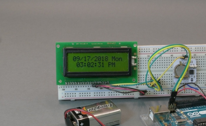
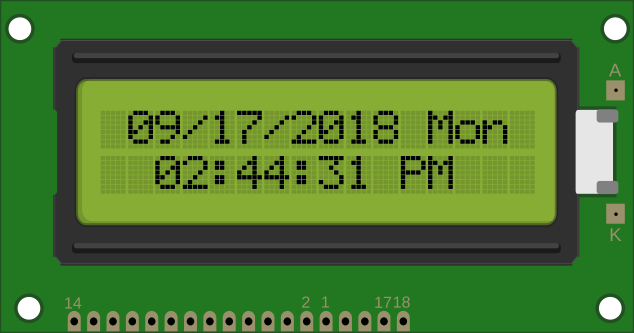
Some time formats are standardized though. For example, you can read about ISO 8601 or Unix time formats. You can check out the xod/datetime library for the format-timestamp node. It formats datetime for use in spreadsheet computer programms. In this example, let’s format date and time as they are shown on the digital clock in the classic American style. Here is the picture of the digital clock we want to make.
Let’s create three additional patch nodes which format our date and time values.
Formatting date #
We start the formatting process from the date. Create a patch for the first new patch node and name it format-date. We want this node to get numbers for a year, month, and day and output them as a single string. Also, we want format-date to separate the date values with the / character.
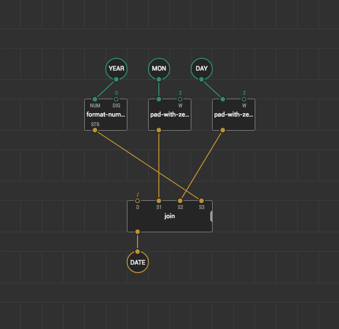
- Add three
input-numbernodes onto the patch and name themYEAR,MON, andDAY. - Add the
output-stringnode onto the patch and name itDATE. - Add the
format-numbernode and link it with theYEARnode. The year values that comes to theYEARpin are of Number type. The Number type values are floating point, and the incoming year value looks like2018.00. We use theformat-numbernode to get rid of those zeroes. If you put the0value to theDIGpin string value of the year becomes2018. - Add two
pad-with-zeroesnodes from thexod/coreonto the patch. Link their input pins withMONandDAY. Thepad-with-zeroesnode transforms a Number value into String adding zeroes before the value. The number of added zeroes depends on the width of the string. The width value is set at theWinput pin. This node is very useful for this guide. The month and day value fields on our display have 2 digit capacity. If we show the12/22/2018date on the screen, it is ok. However, if we show, for example the 3rd of September directly without adding zeroes below the month and day, the text on the screen looks will be3/9/2018. Thus cuts the width of the date by two digits, and the total width of the line on the display screen. Thepad-with-zeroessolves this problem. We put the2width value to theWpin on both nodes, so the 3rd of September looks like03/09/2018. By this, the total width of the line with the date will always be static. - Add the
joinnode onto the patch. With thejoinwe can separate day, month and year by a character of our choice. As we want to separate date values with/, we link the/string constant with theDdelimiter pin. Withjoinwe can also set the order of the year, month, and day representation. As we want theMONvalue to be first,DAYto be second, andYEARto be third, we make proper links betweenjoininput pins and other nodes. After this link thejoinoutput to theDATEoutput-string node.
Formatting weekday #
The unpack-datetime node outputs the number of the weekday depending on the date. To show weekday names instead of numbers we need a node. Create a patch for this node and name it format-weekday.
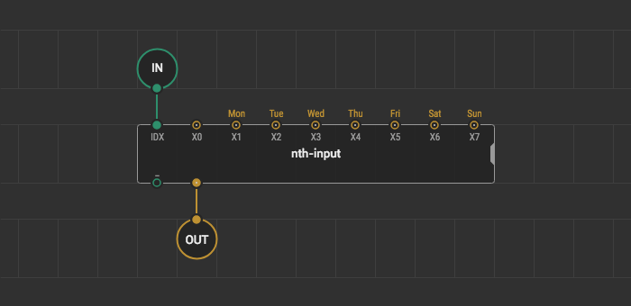
- Add the
input-numbernode for the input weekday number onto the patch. Name itIN. - Add the
output-stringnode for the string name of the weekday onto the patch and name itOUT. - Decide how you name the weekdays for your clock. We name them
Mon,Tue,Wed,Thu,Fri,Sat,Sunand create constant nodes for them. - Add the
nth-inputnode onto the patch. Theformat-weekdaynode outputs the number of weekdays in the range from1to7. So, the Monday number is1, and the Sunday number is7. Thenth-inputnode is great for this example, it outputs the selected value fromXpins based on theIDXindex value. Let the input nodeINbe the index. - Link the
INinput-node to theIDXpin. - Link the weekday nodes to the corresponding
Xpins of thenth-inputnode.
Formatting time #
Ok, we created nodes that format date and weekday. Time is left to format. Create a patch for the new node and name it format-time. This node will take hours, minutes and seconds from the unpack-datetime node and format them as we desire.
- Add three
input-numbernode for the time and name themHOUR,MIN, andSEC. - Add the
output-stringnode for the formatted time in a string form. - Put three
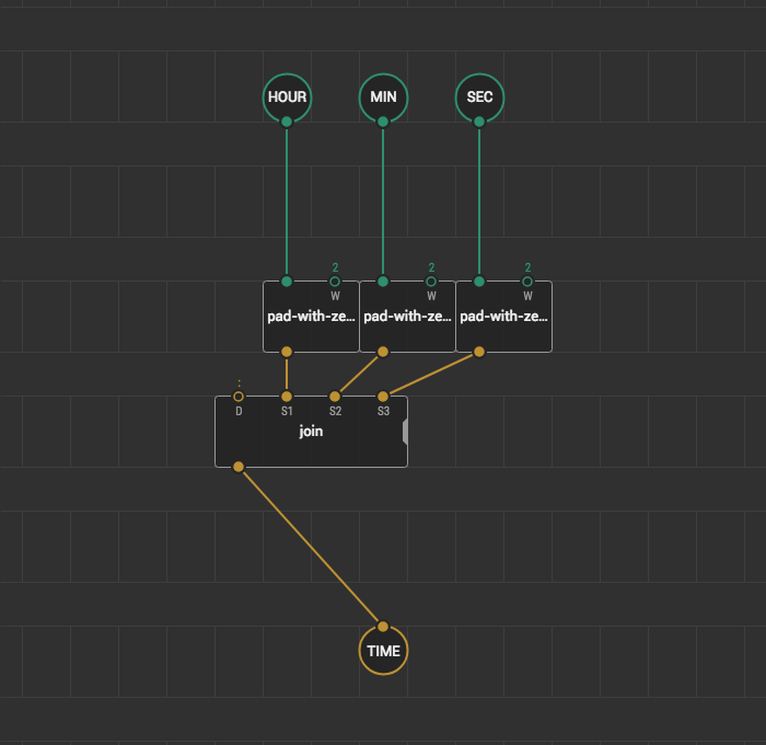
pad-with-zeroesnodes onto the patch and link them withHOUR,MIN, andSECnodes. To display hours, minutes, and seconds in a two-digit format, put the2value to theWpins as we do it in theformat-datenode. - To separate the time values with a colon use the
joinnode. Put the:delimiter into theDpin of thejoinnode. Also, you can use thejointo set the order in which the time is displayed. Make proper links between thepad-with-zeroesoutputs and thejoininputs.
For the American style clock, we decide to use the 12-hour format instead of 24-hour. For the part of the day, we show the AM and PM words on the display screen.
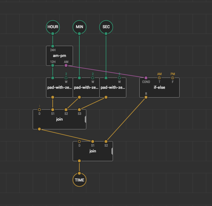
- Insert the
am-pmnode between theHOURinput node and thepad-with-zeroesnode. Theam-pmchanges the hour format from 24 to 12. TheAMpin istrueif it is “before midday” orfalseif it is not. - Add the
if-elsenode onto the patch and set theAMstring value forT, andPMstring value forF. Link theCONDpin with theAMoutput of theam-pmnode. - Separate the time from the
PMandAMlabels with a single space. For this, put anotherjoinnode onto the patch. Put the spacer character to its delimiterDpin. - Link the last
joinwith the nodes above and the output nodeTIMEto finish theformat-timepatch.
Combining the formats #
Format nodes are ready, so let’s put them onto the rtc-example-read patch.
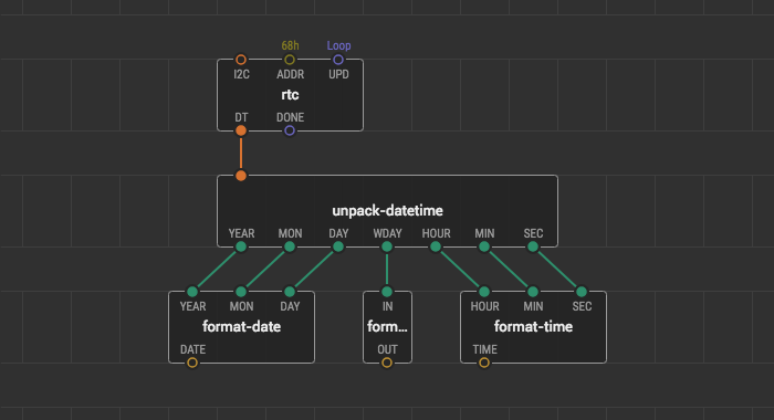
- Put the
format-date,format-weekday, andformat-timenodes, that you’ve just created. Link their inputs to theunpack-datetimeoutputs.
Displaying on the screen #
When the date, time, and weekday are formatted we can show them on the I2C display screen. Let’s show the date and the weekday at the first line of the I2C display, and time at the second line.
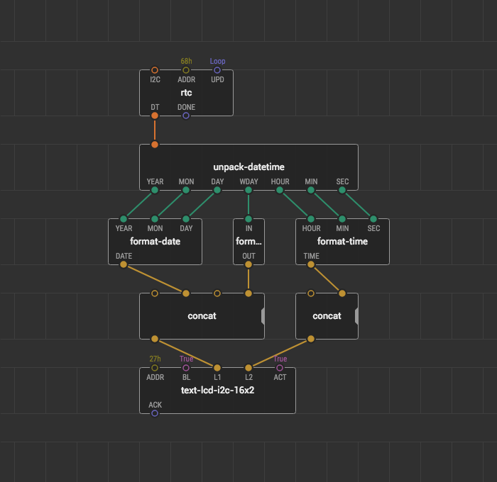
- For the I2C 16x2 display, put the
text-lcd-i2c-16x2node onto the patch. - The screen of the display in this example has 16x2 digits capacity. We align both display lines to the center to make the clock looks better. For this, we put two
concatnodes for each line. There we added two spaces to indent the text from the edge of the screen and one space to separate the day of the week from the date. - Link the second
concatnode of the date and time with theL1pin of thetext-lcd-16x2-i2cnode. The secondconcatnode with theL2pin.
Result #
Upload the rtc-example-read patch to your Arduino board and look what the digital clock you get.
If you encounter any problems trying to repeat the guide, download the prepared project and open it in the IDE.
Conclusion #
We created a digital clock device using xod/datetime and xod/ds-rtc libraries. Try to make your own clock with different styles and timestamp formats.
If you want to practice, find other usages of these libraries. For example, connect a real-time clock to an SD card, log timestamp values using the format-timestamp node, and have a look how it is easy to process timestamps with the computer applications.