Working with Servo Motors
A servo is a special electromechanical device that uses error-sensing negative feedback to correct the action of a mechanism. Servos can be pneumatic, hydraulic and even piezo, but the most common are electric motorized servos or servo motors.
Servo motors are servos with an output rotating shaft. The main purpose of a servo motor is to maintain the output shaft at a given angle or at a certain rotation speed. In general, a servo motor consists of three components: a motor, a position or angle sensor, and a control electronic board. These components vary widely depending on the application type and the required accuracy. A motor can have a gearbox, be DC or AC or even stepper. The angular positioning can be performed by inexpensive potentiometers or high-precision industrial rotary encoders. The control board can perform only basic servo functions or be intelligent and provide detailed feedback containing torque, motor temperature, and other data.
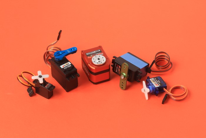
In the DIY-world, the most popular are so-called “hobby” or “RC” servos due to their affordability, reliability, and simplicity of control by microcontrollers. Inside, they have a DC geared motor with a potentiometer positioning the shaft. These servos are controlled by pulse-duration modulation (PDM) signals. The electronics translate the width of a pulse into the shaft position. When the control board receives a move command, the motor rotates until the potentiometer reaches the value corresponding to the commanded position.
There is a special xod-dev/servo library of nodes to work with such servos in XOD.
Quick start node #
To start working with a servo motor the library provides the servo quickstart node.

This node contains all necessary settings that are suitable for almost any hobby RC servo. It is enough to wire a servo to a microcontroller board through any port. The number of this port should be set at the PORT input value of the servo node.
The value at the VAL pin represents the target position for the servo shaft to rotate. This pin expects values in the range from 0 to 1. The 0 value corresponds to the extreme position of the servo shaft in one direction whereas the 1 value corresponds to the opposite direction. For most hobby servo motors made for robots the maximum rotation angle equals 180°. So, at the 0 value on the VAL pin, the node rotates the servo shaft to the position 0°, and at the 1 value to the position 180°.
The true boolean type value at the ACT input makes the servo node reacting to incoming VAL changes. If the ACT value is false the servo shaft is hold at the last received position value.
Quick start examples #
For the servo node the shaft position value can be set in different ways.
You can set it to a constant using the constant-number node.

In this case the servo shaft angle is fixed during the entire operation of the program.

A shaft position value can be entered directly into the value field of the VAL input pin.

Here, the servo horn is also held at the specified angle.

You can use the tweak-number node together with the debug mode and manually set every new position value for the shaft.
The value for a servo can be obtained from other nodes. For example, from the pot node operating a potentiometer. Connect a potentiometer to a microcontroller and link the output pin of the pot node with the input pin of the servo node.

Turn the pot knob to see the servo shaft move.
Advanced servo device initialization #
If you have a non-standard servo motor or you want to precisely configure your servo use the servo-device node.

Hobby RC servo motors can have different rotation angles: from 0 to 120 degrees, 0 to 180, 0 to 270, etc. The extreme servo positions correspond to PDM pulses of a certain width. The pulse width value can lie in the range from 544 to 2400 microseconds, from 500 to 2500, from 1000 to 2000, or other. Most often the maximum and minimum pulse width length values are mentioned in the datasheet of a servos manufacturer.
The servo-device node constructs and outputs a servo-device object of a custom type containing the maximum and minimum pulse length you specify. The lowest pulse width value is set at the Pmin pin and the upper at the Pmax pin. In XOD extreme pulse width values are set to 544 and 2400 microseconds by default. By changing these pin values you can define a servo-device that fits your particular servo motor. Also, they can narrow or extend the operation range if it is permissible by servo design.
Advanced servo rotate #
To execute the rotation of the servo-device, use the rotate node. Link its DEV pin with the servo-device node and set the desired angle value at the VAL pin.

An input pulse signal at the DO pin triggers a rotation command. If the command is acknowledged by the servo device, the movement starts and a pulse signal comes at the ACK output pin. When using the rotate node the servo moves at the maximum possible rotation speed.
Rate and sequence of rotation #
You can adjust the rotation speed of your servo motor with the rotate-slow node. Put the desired angle value into the VAL pin and the required rotation speed rate into RATE.

When you use the rotate node, a command for the servo to rotate to the desired angle is generated just once. Unlike it, the rotate-slow node generates the rotation commands repeatedly and continuously with varying angles until the desired VAL value is reached. The RATE value defines the amount of VAL change per second for the rotation commands.
To achieve correctness the RATE value should be lower than the maximum servo rotation speed. The maximum speed can be found in the servo manufacturer’s datasheet.
For example, the FEETECH FS90 Micro Servo datasheet states that it rotates 60 degrees in approximately 0.12 seconds. This means that the full rotation from 0 to 180 such servo performs in 0.36 seconds. Dividing 1 second by 0.36 you can get the highest RATE of this servo: 2.77. In some cases, the maximum RATE value can be obtained empirically or by trial and error.
The MUX pin of the rotate-slow node has the mutex type. The mutex describes a mutually exclusive resource. It is used to avoid conflicts between nodes controlling long-running rotation processes. In the rotate-slow, the mutex is used to protect the running rotation process from the insertion of external commands generated by other rotation nodes.
Let’s make a patch that rotates the servo from 0° to 180° with RATE set to a quarter of the maximum rotation speed and then in the opposite direction with RATE set to the half of the maximum speed.
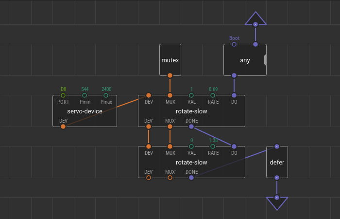
Add a couple of rotate-slow nodes onto the patch. The first node rotates the shaft to 180 degrees. Link it with the servo-device node and set the VAL to 1 corresponding to 180 degrees. To set the quarter of the maximum rotation speed, divide the maximum speed value 2.77 by 4 and put the resulting 0.69 value to the RATE pin.
Link the second rotate-slow node to the DEV bus. The node rotates the shaft backward just after the first rotation is done so link its input DO pin with the output DONE pin of the previous node to make the sequence. The VAL value set to 0 corresponds to 0° and the RATE value set to 1.38 corresponds to the half of the maximum servo speed.
Here two nodes are involved in the rotation of the servo. To make them do not interfere with each other, add a mutex node and link the MUX buses.
The last step is to loop the program using the defer and any nodes. Let’s flash the patch and look at the result.

Current position #
You can find out what position the servo shaft is expected to be at a particular moment. For this there is the position-value node. Use it to obtain the current servo angle from the servo-device.
Let’s extend the previous example with the position-value node.
Add it onto the patch and link it with the DEV bus. The UPD pin sets the update frequency for the current VAL angle. You can monitor the current servo angle continuosly using the watch node together with the debug mode. Upload the improved patch.
Make your robot or project move with servo motors and the xod-dev/servo library. Use the quickstart xod-dev/servo to solve simple tasks or advanced servo development nodes to create complex rotation algorithms.