Creating Analog Sensor Driver Nodes
Many sensors provide measured values as voltage levels. A board can read the voltage level and perform some calculations to convert the voltage to reasonable units.
This article guides you through a process of adding support for such sensor. To do this, we’re going to create a new patch node. It is implied that you already know how to create patch nodes.
Start with creating a new project, or open the project you worked on while learning to develop patch nodes.
The task #
To demonstrate the process, let’s create a new node to read a popular GP2Y0A02 (yep, not a very elegant name) infrared range meter by Sharp. This guy:
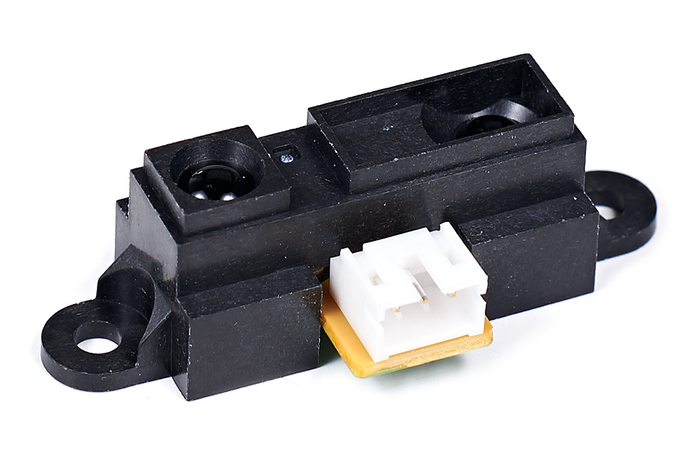
Our purpose is a node which provides distance to an obstacle in meters. Actually, the xod/common-hardware library already contains the node, but for the sake of example, let’s imagine there is no such node yet.
Pull useful data from a single sensor #
First, read the datasheet and understand the math behind voltage-to-value conversion.
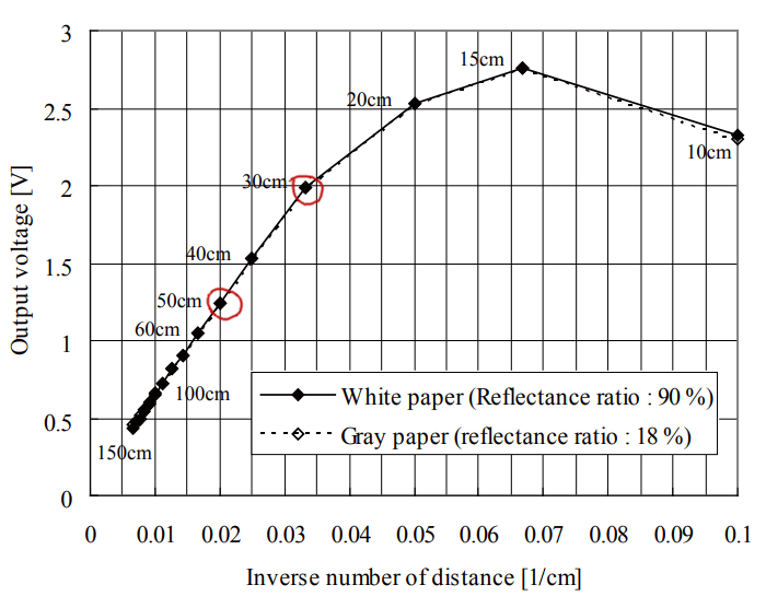
In our particular case, we see that the “Inverse number of distance” almost linearly depends on “Output voltage” in sensor’s working range (20 to 150 centimeters). The points outlined in red are on the grid and thus convenient to build a proportion. Finally, our computation plan is:
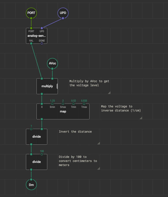
- Convert analog input value to a voltage level value
- Map the voltage to inverse distance: [1.25, 2.00] → [0.020, 0.033]
- Invert the distance
- Convert centimeters to meters
So, in XOD we need to read analog values from the sensor, do the math, and we’ll get desired distance value in meters. While testing, use the watch nodes to observe the results and verify correctness. Here is our patch:
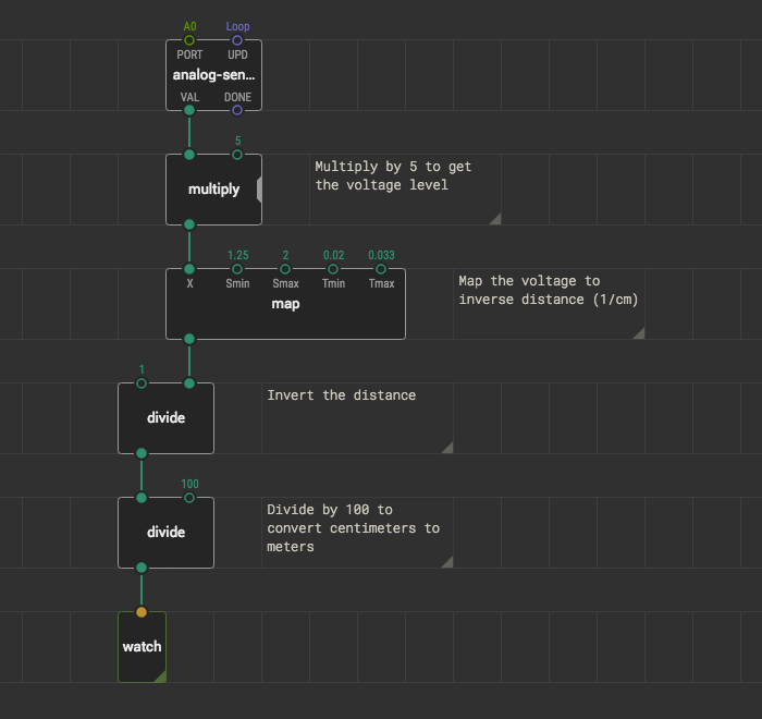
Bind the PORT value of analog-sensor to the board pin number you’ve connected the sensor. Upload with debugger enabled, slowly move a book or sheet of paper ahead of the sensor and observe value change. Do measurements look realistic? Cool! We have a “body” for our new node.
Wrap the reading into a node #
The current program works but has the PORT value hard-coded and contains the watch node not everyone would be interested in. Let’s move from the draft to a complete solution.
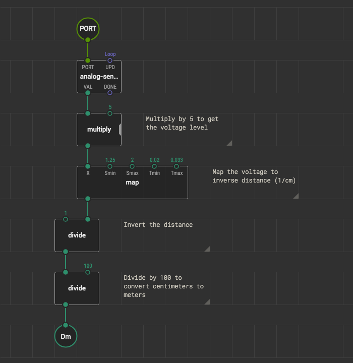
Create a new patch and name it like gp2y0a02-range-meter.
⟨cryptic-part-id⟩-⟨human-name⟩ naming convention. It
simplifies further node search and identification on a patch.
As you did before, cut/paste all nodes except the watch from the main patch to the gp2y0a02-range-meter. Again, we need few terminals to interact with the node. At the very least they are PORT value and the result. Don’t forget to give them sensible labels.
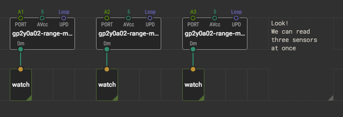
Switch back to the main. Drag and drop the gp2y0a02-range-meter node there. That’s our range meter, and it provides distance values. Link its output pin to the watch. Upload the program with the debugger and verify the watch shows actual distance.
Allow more tweaks #
Also, not every board has 5 volts as it’s upper measurement limit. Some use 3.3 volts; others depend on a battery charge. It is a fact not related much to our node, so we’ll let a user specify ADC voltage. Extra input-number would make it configurable.
One more thing. It’s highly recommended to expose the update (UPD) input as well. That way a node user can control when and high often to read the sensor. Use an input-pulse for it.
Set the defaults #
Although measured voltage setting is up to a user from now on, we want to provide a sensible default for it: 5 volts. The value will be used until a user overrides it. To bind a default value, select the terminal node and set the desired value in the Inspector.
Likewise, set the default value for the UPD terminal to “Continuously.”
The result #
We have made a complete solution to read a particular sensor model. Next time you would hook range meters into a project you have not to recall all the math behind the raw signal conversion.
Now you should be able to make similar nodes for dozens of sensors. The difference is in math only. Consult the part datasheet to understand it.