Simple Traffic Light Example
A traffic light is a good example of a device which does its job sequentially. In its simplest form a traffic light has three states:
- Green — go
- Yellow — stop if you can
- Red — stop!
Each state is active for some time interval and when done everything starts from the beginning and repeats again and again.
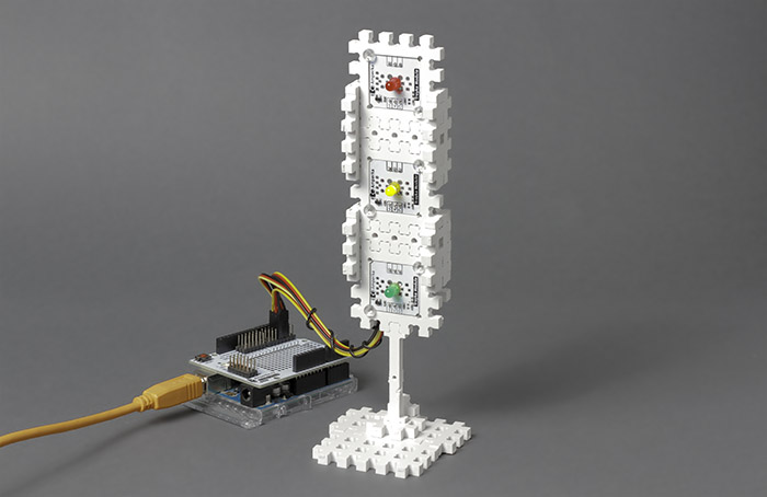
Let’s make a traffic light device model with few electronic parts and XOD.
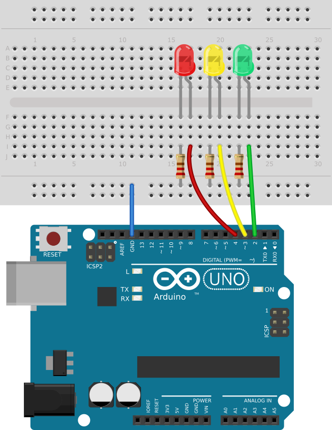
Circuit #
Program structure overview #
Create a new project in XOD and name it something like my-traffic-light. Now you have a program with a single patch main. What’s next?
We have a state machine that we’re going to implement. There are several ways to do the job. Let’s consider one of them. The basic idea is to have one patch node per state and a joining patch that will wire the state patch nodes together. In our case:
state-greenstate-yellowstate-redmain— the joining patch
We plan to (a) create drafts for all state patches, (b) craft the main patch, and (с) after that complete the state patches. You can do things in reverse if it makes more sense to you.
We already got the main, so create the state patches. Hit “File → New Patch” (or Ctrl+N) and enter the new patch name. Repeat three times.
state- prefix is not
required doing so is a good idea. It shows the patch designation and simplifies
program understanding.
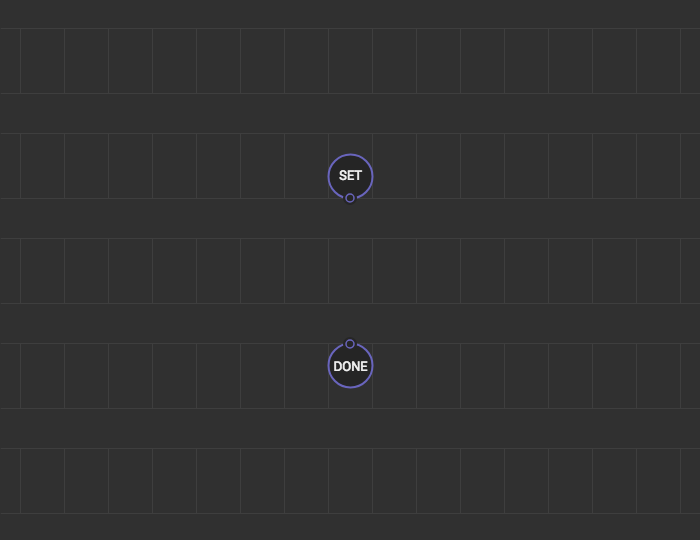
Now we need a mechanism allowing patch nodes to talk to each other. A common idiom is to make a pulse input on a state patch to enter that state and add pulse outputs to notify about state completion.
Add a pair of xod/patch-nodes/input-pulse and xod/patch-nodes/output-pulse to each state patch:
Now each of our states has an input and output. We can wire them in a daisy chain so that when one state completes its job, it gives the control to the next state. Let’s do it on main:
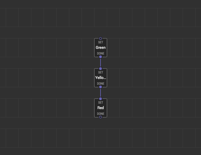
We gave shorter labels “Green,” “Yellow,” and “Red” to our nodes so the text could fit the width.
Nice, isn’t it? You see how the device should work graphically.
Implementing state patches #
OK, we’ve got a basic state patch skeleton, let’s fill it up. You’re going to answer few questions before doing that.
- What should a state do once entered?
- When should it exit?
- What should it do right before exit?
In our case, when we enter a state it should turn on the corresponding LED. Then it should wait few seconds, turn the LED off and then exit. Pretty simple. Do it for the state-green:
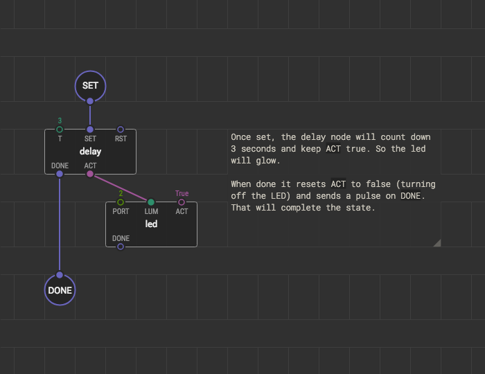
Set proper values for led’s port (port 2) and T of the delay (3 seconds is fine for the experiment).
We have done with the green. Are yellow and red differ anyhow? Not in our case. Just replicate the patch on state-yellow and state-red. Do not forget to adjust PORT and T values. Use copy/paste to do it quickly.
Running the sequence #
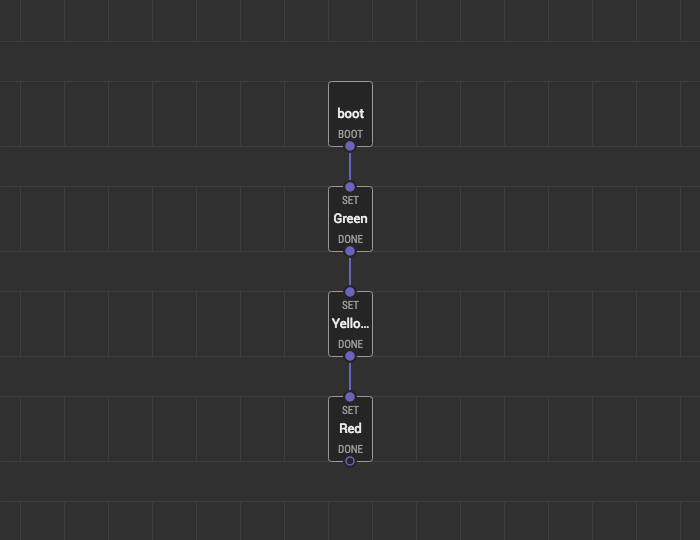
We are almost done. The only thing left is triggering the execution. Look at the main again:
Although the states are correctly chained, nothing would trigger entering the first state (i.e. the state-green). We want our traffic light to start its job right when the device is powered up. So a pulse from the boot node is the best choice:
Finally, upload the program to your board and see how they behave.
Whoa, it works! Almost. Once the red state completes the traffic light does nothing. Let’s fix it
Making a cycle #
The device suspends after the last state because nothing returns it back to the first state. We could link the last state DONE pulse to the first state SET pulse to complete the loop, but unfortunately, XOD does not allow to do so.
XOD forbids cycles in a program graph to avoid possible deadlocks. No deadlocks are possible in our particular scenario because we use delay nodes but XOD is not smart enough to figure it out.
Luckily so-called “defer nodes” are here to help us. They can break any cycle and tell XOD: “Hey, I’m the point where you can take a breath if a deadlock happens”.
We deal with pulses, so we will use the defer-pulse node to break the cycle.
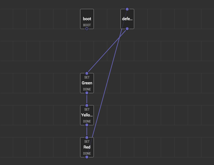
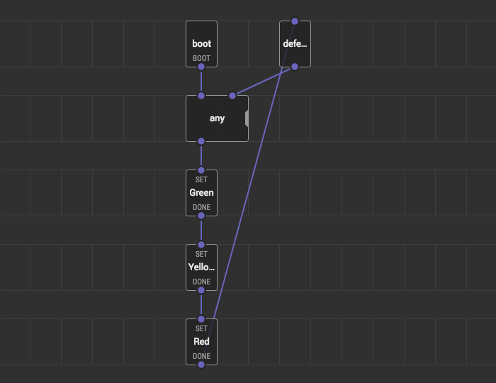
Oops. The first state-green node input is not allowed to have links from the boot and defer-pulse at the same time. We can easily solve it by adding an any node:
Whew! Well done. Upload the program and see how it works. Play with timeout values, try to start the sequence from another state, add three more LEDs to form a complementing traffic light. Have fun!
Result #
If you have got problems trying to repeat the guide, download the prepared project and open it in the IDE.
Conclusion #
Doing things sequentially in XOD could appear hard at first sight. Yes, it’s a bit harder than in traditional imperative languages, but not so complicated if you would remember the pattern:
- Understand your sequence states
- For each state make a patch node
- On each state patch, use pulse inputs and outputs to enter and exit the state
- Make a joining patch which wires all states together
- Define an entry pulse for the first state