SSD1306 displays
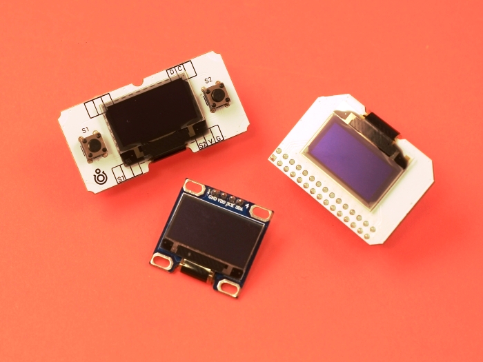
The SSD1306 display is an OLED that is controlled by the SSD1306 micro-chip driver, which acts as a bridge between the display matrix and the microcontroller. Due to the natural light of the organic LEDs in the matrix, SSD1306 displays are bright and have a wide viewing angle. These tiny displays are similar to those monochrome used at the old cell phones. Despite the size, these displays are very functional and capable of displaying complex images. The accessibility of this model makes it the most popular in the Arduino world and hobby electronics.
The displays breakout boards belong to the SSD1306 family can have the following parameters:
- Display resolution:
- 0.91" (128x32 pixels);
- 0.96" (128x64 pixels);
- Display colors (color mode):
- Monochrome, black and white;
- Two colors. OLEDs may have different colors, for example, one part of the display is black/white, and the other is black/yellow;
- Interfaces:
- SPI interface (software of hardware);
- I²C interface;
To work with the SSD1306 family displays XOD provides the xod-dev/ssd1306-display library.
Quick start node #
The library provides the quickstart node ssd1306-128x64-i2c for the SSD1306 I²C display with the 128x64 pixels resolution.
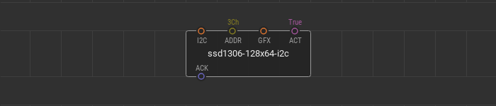
This node contains everything you need to start working with the display. You only have to connect your display to the microcontroller via an I²C bus and put the I²C address value of the byte type to the ADDR pin field.
The GFX input pin of the graphics type specifies the graphics to render and display on the device screen. The GFX awaits a branch of the tree of graphical elements created using the graphics library. The boolean value at the ACT pin is responsible for the display screen update due to change of the incoming graphics at the GFX pin.
Quick start example #
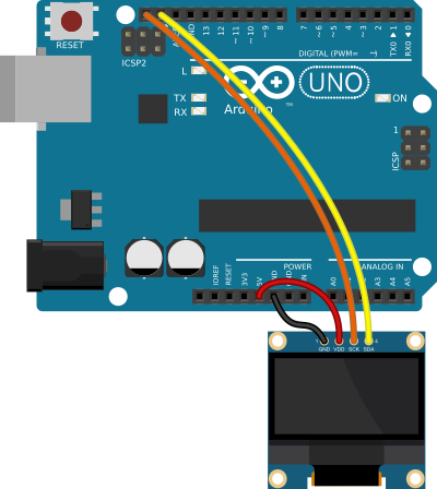
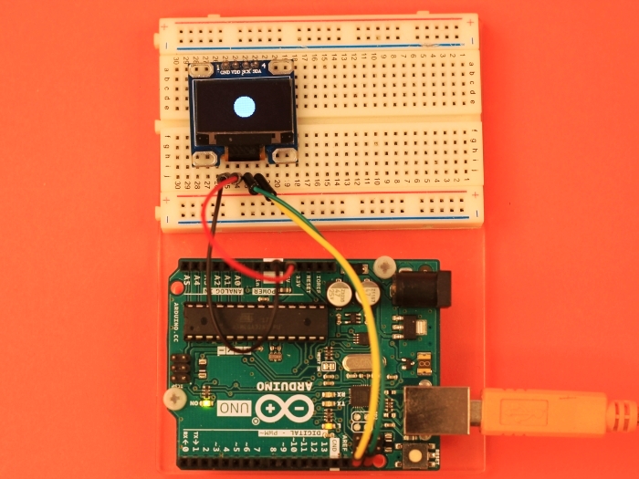
Here is a simple example of using the quick-start node. Connect the display to a microcontroller according to the wiring scheme.
Let’s display a white filled circle in the center of the screen.
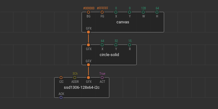
Create an empty patch and put the ssd1306-128x64-i2c quickstart node onto it. The display from this example has the 3C hexadecimal I²C address so we put the 3Ch value to the ADDR pin.
Using the XOD graphics library, create a new canvas with the size of a display screen. The width W of the canvas is 128 and the height H is 64. The display is monochrome, and you can leave the default colors of the scene untouched. The background color BG is black (#000000) and the foreground color FG is white (#FFFFFF).
To add the filled circle to the scene, place the circle-solid node onto the patch. To make this node be a part of the graphic tree, link its GFX pin with the GFX pin of the canvas. Set the circle coordinates for the center of the screen, 64 for X, and 32 for Y. The radius R can be random, for example, 15.
The scene is ready. Connect the GFX output pin of the circle-solid node to the GFX pin of the quickstart node. Take a look at what the patch should be.
Upload this patch and see what is displayed on the screen of the device.
You can change the position of the circle on the canvas using tweaks. For example, add two tweak-number nodes for the X and Y circle coordinates. Flash the patch in debug mode and manage the coordinates of the circle center.
The parameters of graphic nodes can be changed using other nodes. For example, let’s replace the filled circle with a text field and control its size on the screen with a potentiometer.
Remove tweak nodes from the patch. Replace the circle-solid node with the text node from the xod/graphics library. Next, set the text string, let it be "Hello world!". Enter it at the S pin of the text node. Add the pot nodes and multiply node to control the scale of the text. The potentiometer is connected to the A0 Arduino port. Link the multiply output with the SCL pin.
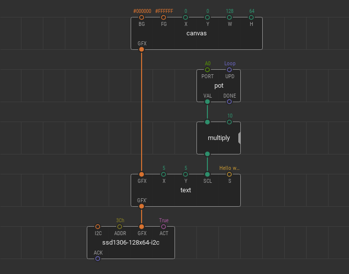
By multiplying the output value of the pot node by 10, you can increase SCL size ten times. Upload the patch and manage the changes.
Advanced OLED device initialization #
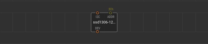
If the quickstart nodes doesn’t suit your task try to operate developer nodes from the xod-dev/ssd1306-display library. Initializie your display using the ssd1306-128x64-i2c-device device node from the library. It is only necessary to specify the I²C address of the device.
Render the scene #
The render node is your main tool to display graphic scenes. The render processes a single branch of the graphic tree created using the graphics library, renders it, and displays at the device.
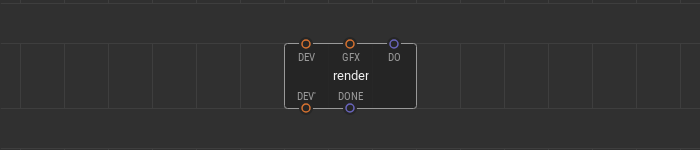
A graphic tree branch to render links to the input GFX pin. A pulse signal at the DO pin is a trigger to process the graphic scene and display it. If the scene is rendered, a pulse comes to the DONE output pin.
Use multiple render nodes simultaneously. Processing various branches of the graphic tree at a different time, you can show dynamic graphic scenes at the screen.
Here is the example of a three render nodes use. The tree of graphic elements consists of a canvas and two point on it. The device node and three nodes render are linked together in a daisy chain. All render nodes have different triggering algorithms at their DO pins.
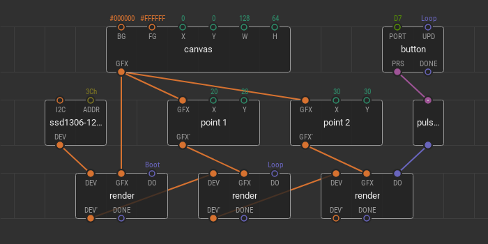
The first render is on boot; it fills the display screen with a specified canvas only once — after powering the device. The second render is responsible for point 1 on the canvas. Its trigger is set to loop. It means that any changes in the point 1 position are immediately shown on the screen. The third render is responsible for displaying the point 2 and its trigger is linked to the button. Here you can also change the point 2 position, but the changes are displayed only after the button click.