Images in XOD
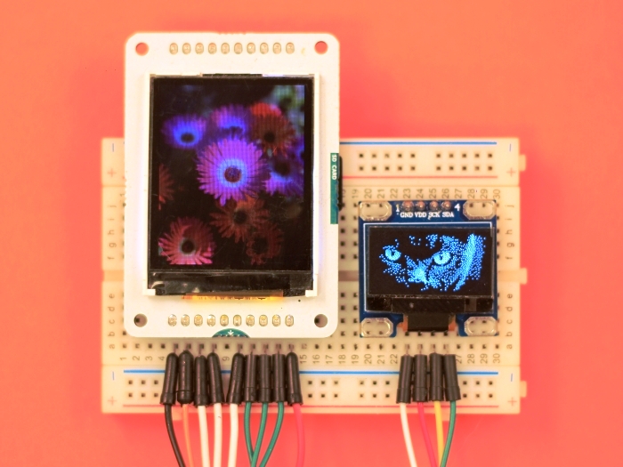
With the graphics library, you can display various images and icons on your display screen.
By now, xod/graphics supports only one way to display images. It is reading bitmap images stored as bitmap arrays of pixel data in the nonvolatile flash memory of the microcontroller.
Bitmap node #
In XOD, any bitmap image is a node.
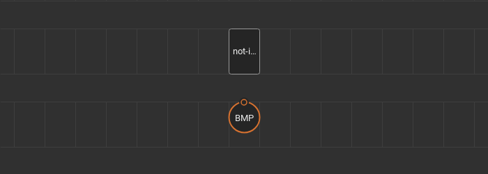
This node has a patch with the output terminal of the Bitmap type. And the not-implemented-in-xod marker node with the following template C++ code inside:
// define `bitmap` inside node's namespace to avoid clashes
nodespace {
    static const unsigned char bitmap[] PROGMEM = {};
}

node {
    Bitmap myBitmap = Bitmap(bitmap, colorDepth, width, height, keyColor);

    void evaluate(Context ctx) {
        emitValue<output_OUT>(ctx, &myBitmap);
    }
}
A new image is created by calling Bitmap myBitmap = Bitmap(bitmap, colorDepth, width, height, keyColor); constructor which awaits five parameters:
bitmap, a pointer to the raw bitmap array of the image;colorDepth, an integer value that sets the color depth of the bitmap image. It can be0- black and white image,1- color image, and2- color image with the key color specified;width, a width of the bitmap image in pixels;height, a height of the bitmap image in pixels;keyColor, a two-byte value of the color mask of the image. This parameter is specified if thecolorDepthvalue is2. If there is a color mask, pixels of the image with the specified color are not rendered. The color mask makes it possible to display bitmap images of any geometric shape.
Images can be color or black and white, depending on the color depth of your display. The color image is stored as a byte array where each pixel is represented by two-byte (RGB565) color value in the form of RRRRRGGG:GGGBBBBB. Black and white images are byte arrays either, but here each pixel has its bit, and the pixel color (white or black) determined by the state of bit (0 or 1).
Image node #
To render a bitmap node, use the image node.
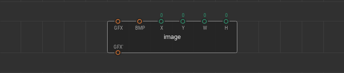
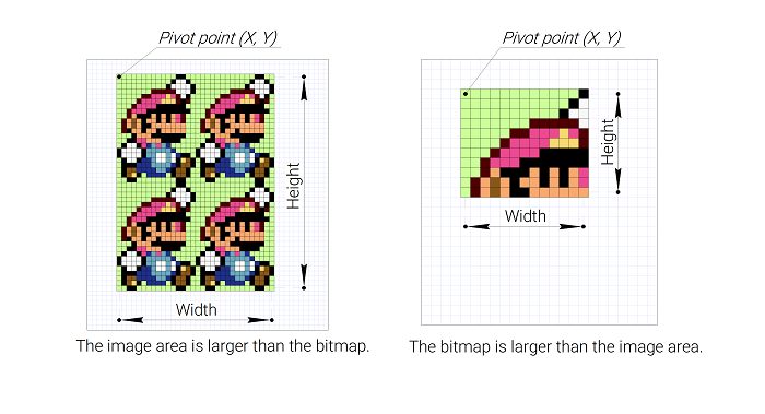
The image node defines a rectangular shape area on a canvas. During the rendering process, this area fills up with the specified bitmap image. The area is set on canvas by a pivot point (X, Y), which is its upper-left vertex, width W, and height H. By GFX pins, the image node takes a part of the tree of graphic elements of the scene as well as other graphic nodes in the graphics library. A BMP pin of the Bitmap type. This pin links the image node to a specific bitmap that should be rendered.
If the actual geometric dimensions of the image stored in the bitmap array are larger than the specified area, then only a part of the image is displayed on the screen. On the other hand, the image area is tiled with the original bitmap if the specified area is larger than the bitmap size.
Embedded icons set #
The graphics library has a small set of example icons to get acquainted with the bitmaps.
Ten 16x16 color icons, five of them with the colorDepth equal 2 and 0x0000 color mask:
![]()
- The “Heart” icon.
heart-16x16-rgbandheart-16x16-rgbawith mask color; - The “Temperature” icon.
temperature-16x16-rgbandtemperature-16x16-rgbawith mask color; - The “Humidity” icon.
humidity-16x16-rgbandhumidity-16x16-rgbawith mask color; - The “Warning” icon.
warning-16x16-rgbandwarning-16x16-rgbawith mask color; - The “Wi-Fi” icon.
wifi-16x16-rgbandwifi-16x16-rgbawith mask color.
Five 16x16 black and white icons:
![]()
- The “Heart” icon.
heart-16x16-bw; - The “Temperature” icon.
temperature-16x16-bw; - The “Humidity” icon.
humidity-16x16-bw; - The “Warning” icon.
warning-16x16-bw; - The “Wi-Fi” icon.
wifi-16x16-bw.
You can study the structure of these icons to create your images.
Making own bitmap node #
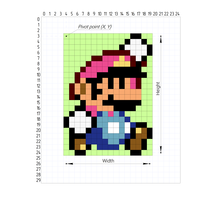
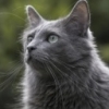
How to create your own Bitmap node for an icon or image? Let’s assume that you want to make a node containing the 100x100 pixels image of a cat.
First of all, make a new patch for the image and name it, for example cat. Put the not-implemented-in-xod node and output-bitmap node from the xod/graphics library onto the patch. Edit the not-implemented-in-xod node. Use the C++ template code above as the starting point.
Find the source image and resize it to dimensions you need using a computer. In this example, the source image is a .JPG file.
Now you need to convert the source image file to a byte array of pixel data. It is tough to do this manually, so many ready-made online web services are offering such features. For example littlevgl.com or digole.com. In XOD, color images have a resolution of 2 bytes per pixel (565 color), so select the correct conversion format.
After converting, you get a long sequence of bytes. This sequence is your converted image. Put this sequence in the static const unsigned char bitmap[] PROGMEM = {}; C++ array value in the node implementation.
static const unsigned char bitmap[] PROGMEM = {
    0x42,0x26,0x42,0x26,0x3a,0x05,0x39,0xe5,0x39,0xe5,0x39,0xe5,0x39,0xe5,0x3a,0x05,0x42,0x25,0x42,0x45,0x4a,0x65,0x52,0xa6,0x52,0xc6,0x5b,0x06,0x5b,0x26,0x5b,0x26,0x63,0x26,0x63,0x26,0x5b,0x06,0x5b,0x26,0x5b,0x06,0x5b,0x06,0x5b,0x27,0x5b,0x27,0x63,0x47,0x63,0x28,0x63,0x48,0x6b,0x67,0x6b,0x66,0x6b,0x67,0x6b,0x88,0x6b,0xa8,0x6b,0xa7,0x6b,0x87,0x6b,0x87,0x6b,0x88,0x6b,0x87,0x6b,0x87,0x6b,0x88,0x6b,0x88,0x63,0x67,0x63,0x47,0x5b,0x27,0x5b,0x07,0x52,0xe6,0x52,0xc6,0x52,0xa6,0x4a,0x85,0x4a,0x85,0x4a,0x65,0x42,0x45,0x42,0x45,0x42,0x45,0x4a,0x65,0x4a,0x86,0x4a,0xa6,0x52,0xa6,0x52,0xa6,0x52,0xa6,0x4a,0xa6,0x4a,0x86,0x4a,0x65,0x4a,0x65,0x42,0x45,0x42,0x25,0x39,0xe5,0x39,0xc4,0x31,0xc4,0x31,0xa4,0x29,0xa4,0x31,0xa4,0x42,0x27,0x6b,0x6d,0x94,0x72,0x84,0x10,0x73,0x6d,0x6b,0x4c,0x8c,0x30,0x94,0x71,0x5a,0xca,0x42,0x27,0x31,0xe5,0x29,0xa4,0x31,0xa4,0x31,0xa4,0x31,0xc5,0x31,0xc4,0x31,0xe5,0x39,0xe5,0x39,0xe5,0x3a,0x05,0x42,0x26,0x42,0x46,0x42,0x67,0x4a,0x67,0x4a,0x87,0x4a,0xa7,0x4a,0x87,0x4a,0x87,0x4a,0x87
    // Part of the sequence is hidden for readability
    ,0x18,0xe3,0x18,0xe3,0x18,0xe3,0x18,0xe3,0x21,0x03,0x21,0x24,0x29,0x44,0x29,0x64,0x29,0x65,0x29,0x85,0x31,0x85,0x39,0xc6,0x42,0x27,0x4a,0x48,0x4a,0x89,0x52,0x89,0x52,0x89,0x52,0xca,0x5b,0x0b,0x73,0x8d,0x84,0x30,0x9c,0xf3,0xad,0x54,0xb5,0x96,0xb5,0x96,0x9c,0xd3,0x8c,0x31,0x73,0x8e,0x63,0x0c,0x5a,0xeb,0x62,0xec,0x5a,0xab,0x4a,0x28,0x39,0xc7,0x31,0xa6,0x39,0xc6,0x39,0xc7,0x39,0xe7,0x31,0xa6,0x31,0x86,0x31,0x85,0x21,0x04,0x18,0xe3,0x29,0x45,0x29,0x45,0x18,0xe3,0x18,0xc2,0x18,0xc3,0x18,0xe3,0x18,0xe3,0x29,0x44,0x18,0xe3,0x18,0xc3,0x10,0xa2,0x18,0xe3,0x21,0x04,0x18,0xc3,0x21,0x04,0x21,0x24,0x21,0x24,0x21,0x04,0x21,0x04,0x18,0xc3,0x18,0xe3,0x21,0x04,0x21,0x04,0x21,0x24,0x21,0x04,0x21,0x24,0x31,0x86,0x21,0x24,0x18,0xe3,0x18,0xc3,0x21,0x04,0x29,0x65,0x29,0x65,0x31,0x86,0x31,0x86,0x31,0x86,0x29,0x65,0x31,0x86,0x31,0x86,0x31,0xa6,0x31,0x86,0x21,0x04,0x21,0x04,0x31,0x86,0x39,0xc7,0x39,0xe7,0x39,0xc7,0x39,0xc7,0x39,0xe7,0x31,0xa6,0x29,0x45,0x21,0x24,0x31,0x86,0x39,0xe7,0x4a,0x49,0x52,0xaa,0x52,0x8a
};
Then set the necessary parameters in the bitmap constructor. The first parameter, a pointer to the array, can be left untouched. The second parameter is colorDepth. We have a color image without a color mask, so choose 1. The third and fourth parameter defines bitmap width - 100 pixels and height - 100 pixels. We can skip the fifth parameter because we don’t use the color mask.
// ...

node {
    Bitmap myBitmap = Bitmap(bitmap, 1, 100, 100);

    void evaluate(Context ctx) {
        emitValue<output_OUT>(ctx, &myBitmap);
    }
}
That it! The node with the image is ready.
- For a color image; Find out the total number of pixels (bitmap width * bitmap height) and multiply it by two since, in XOD, a colored pixel is stored as a two-byte (RGB565) color.
- For a black and white image; First, calculate how many bytes a single row of pixels takes up. In a black and white image, pixels are stored in bits. Divide the image width by eight and round the result to a larger integer. Multiply the rounded value by the image height.
For example, the cat bitmap is a color image that is 100 pixels wide and 100 pixels high. Let’s calculate how much space this image takes in memory, 100 × 100 × 2 = 20 KB of flash memory. It is a huge chunk, and you can’t display such an image on the Arduino Uno. But for high capacity controllers as Arduino Mega 2560 or ESP8266 controllers, it is suitable.
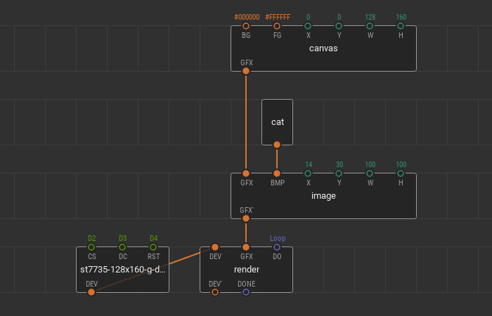
Let’s show the created image on the ST7735 display screen. For this, create a new patch and put the st7735-128x160-g-device and render nodes from the xod-dev/st7735-displaylibrary. Then make a tree of graphic elements. Put the canvas and image nodes from the xod/graphics library. Set up canvas width to 128 pixels and height to 160 pixels to fit the device screen. Link the created bitmap cat node with the BMP pin of the image node. Set the width and height of the image field to 100 pixels. Put the image in the middle of the canvas. For this, set the coordinates of the upper-left corner of the image to (14, 30).
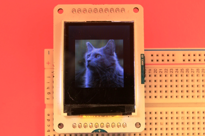
Upload the patch and look at screen.
Color masking #
Now let’s try to make and display the image with a color mask. As a source file, we use the color Arduino logo 100x100 pixels.
![]()
As you can see, this image has a red color (#FF0000) along the outline of the logo. It’s the color that we use as a mask, making red part of the image “invisible” on the display screen.
Create one more bitmap image node and name it logo. Convert the source file to the array of bytes as we did making the cat node. But this time, we change some parameters in the Bitmap constructor.
// ...

node {
    Bitmap myBitmap = Bitmap(bitmap, 2, 100, 100, 0xF800);

    void evaluate(Context ctx) {
        emitValue<output_OUT>(ctx, &myBitmap);
    }
}
If we want to make an image with a mask, we set the colorDepth value to 2. At the last constructor parameter, we specify the two-byte keyColor of the mask, which is 0xF800. This color corresponds to the pure red RGB color #FF0000.
Let’s expand our previous patch to display images on the ST7735 screen.
Change the BG background color of the scene on the canvas node. For example, to the #FF00FF pink. It gives us a better view of the outline of the masked image on the screen. Add the logo image node onto the patch. Also, add the button and generic if-else node. Link the nodes, as shown below.
![]()
By clicking on the button, we are going to change the image in the center of the screen. From the cat image to the logo with a color mask. Upload the patch to the microcontroller and take a look at the result.
- Create and render different bitmap images on your display devices, but ensure that your MCU has enough memory for that.
- Use black and white images for black and white displays like SSD1306 display or to optimize the memory usage on the low memory microcontrollers.
- Color images can have a color mask. Create images with masks to achieve different visual effects.